АэПТРЧ ЙшАќРЬ Pipe RackРЛ ХыАњЧв АцПь, СТУј БзИВПЁ КИРЮ ЙйПЭ ААРЬ, ПЦиУЂ ЗЎРЬ ШэМіЕЧЕЕЗЯ ЙшАќ RouteИІ Loop
И№ОчРИЗЮ ИИЕщАэ, Two-Guide One-Stop ЖЧДТ One-Guide 3-Way Directional Stop SupportИІ ЛчПыЧбДй. РЬПЭ ААРЬ
ЙшАќ LoopРЧ РќШФИІ Two-Guide One-StopРИЗЮ БИМгЧЯИщ ЙшАќРЧ LoopПЁМ ПЦиУЂРИЗЮ РЮЧЯПЉ ЙпЛ§Чб ForcesПЭ MomentsДТ
И№ЕЮ ТїДмЕШДй. СЛ Дѕ ОіЙаШї ИЛЧЯИщ, Two-Guide One-StopИІ ЕЮИщ (РЇ БзИВПЁМ MzПЁ ЧиДчЧЯДТ) ЙшАќРЧ СјЧрЙцЧтПЁ
ДыЧб (Torsional) MomentИІ СІПмЧб И№Еч ЙцЧтРЧ ForcesПЭ MomentsАЁ ТїДмЕШДй. ТїДмЕЧСі ОЪАэ Two-Guide One-StopРЛ
ХыАњЧб Torsional MomentДТ ЙшАќРЬ СјЧрЙцЧтРЛ ЙйВйДТ (ВЊРЬДТ) КЮРЇПЁМ МвИъЕШДй.
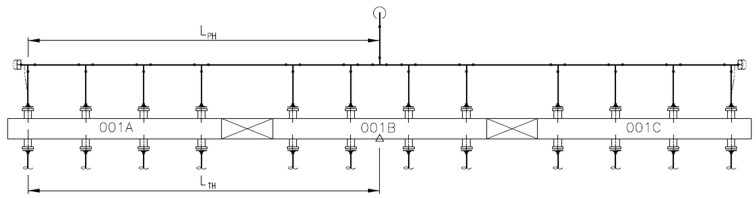
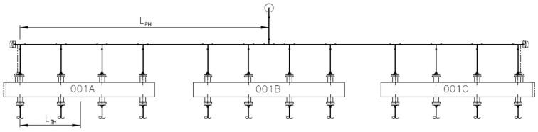
ЕћЖѓМ Two-Guide One-StopРК ЙшАќРЧ МГАшБИПЊРЬ ДйИЅ (Battery Limit) АцАшСіСЁРЧ SupportЗЮ ЛчПыЕЧБтЕЕ ЧЯАэ,
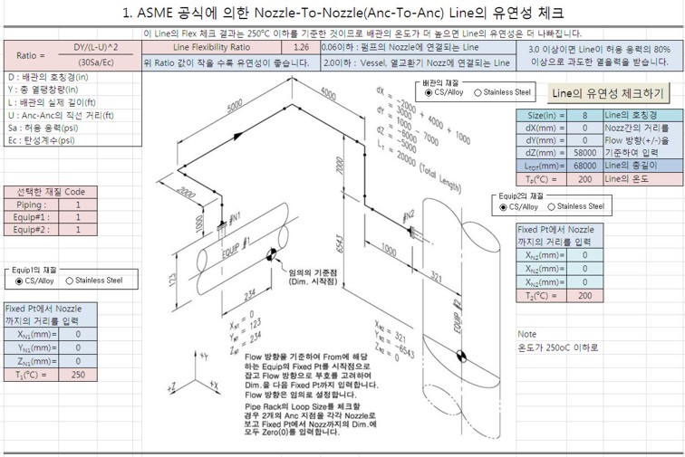
ЖЧ Stress Iso DwgРЬ 10Рх РЬЛѓРИЗЮ ИЙРК ЙшАќ RoutineРЛ Analysis Чв АцПь, Мв БдИ№РЧ (Problem) Run-PackageЗЮ
КаИЎЧЯБт РЇЧиМ СОСО ЛчПыЕШДй. Node NoАЁ 1000РЛ ГбБц СЄЕЕЗЮ Бз БдИ№АЁ ХЋ ЙшАќ SystemРК РћР§Чб РЇФЁПЁ Two-Guide
One-StopРЛ ЕЮОю МвЧќРИЗЮ КаИЎЧЯАэ РРЗТЧиМЎРЛ МіЧрЧЯДТ АЭРЬ ССДй.